1. Introduction
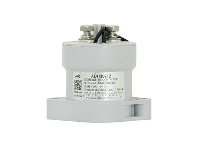
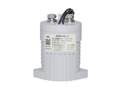
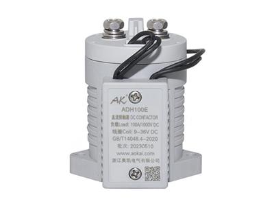
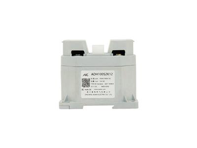
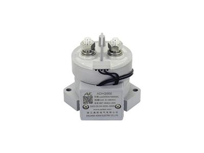
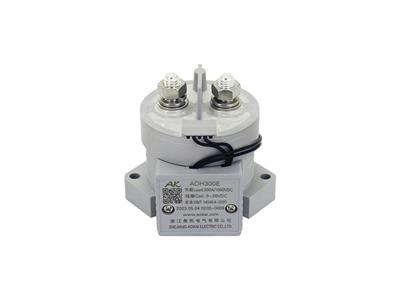
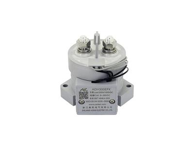
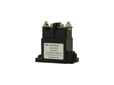
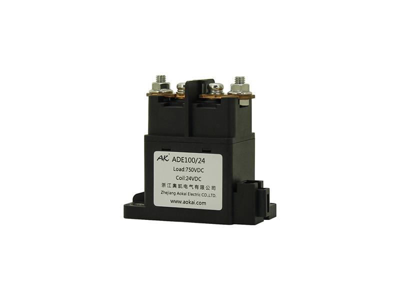
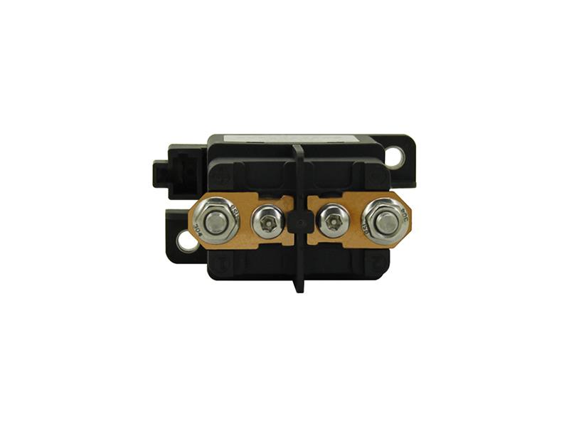
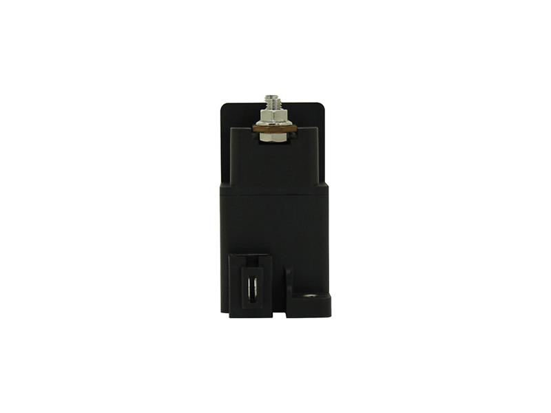
This series DC Contactor Relay is used in the DC voltage power control fields, such as new energy vehicles, construction machinery, photovoltaic systems, wind power intelligent equipment, battery charging and discharging systems, charging piles, etc.
2. Features
• Using ceramic brazing technology, the contact part is filled with mainly hydrogen gas to effectively prevent contact oxidation and burnout. The contact resistance is low and stable, and the contact part can meet the IP67 protection grade.
• 100A 85ºC long time current carrying capacity.
• The insulation resistance is up to 100MΩ (1,000VDC), the withstand voltage between the contact and the coil is 4kV.
• Compliant with IEC 60664-1, GB/T14048.1 and GB/T14048.4 requirements.
• Compliant with RoHS (2015/863/EU), REACH (1907/2006/EC) requirements.
• Safety certificate: CE, CCC.
3. Specification
|
Main Contact Specifications |
|
|
Contact Arrangement |
1K (1NO) |
|
Contact Polarity |
Non-polarity |
|
Contact Resistance |
≤0.5mΩ (at 100A) |
|
Max. Switching Voltage |
1,000VDC |
|
Max. Breaking Current |
1,000A (300VDC) 1 Ops |
|
Electrical Endurance (Resistive Load) |
1,000 Ops (750VDC, 100A) |
|
6,000 Ops (450VDC, 100A) |
|
|
Mechanical Endurance |
200,000 Ops |
|
Withstand Current |
100A, Continuous |
|
120A, 2h |
|
|
200A, 10min |
|
|
400A, 2min |
|
|
600A, 30s |
|
|
Dimension |
81.5mmx39.6mmx78.3mm |
|
Performance Parameters (at 23℃) |
||
|
Pickup Voltage |
≤75%Us |
|
|
Dropout Voltage |
≥8%Us |
|
|
Pickup Time |
≤30ms |
|
|
Contact Bounce Period |
≤5ms |
|
|
Dropout Time |
≤10ms |
|
|
Dielectric Strength |
Between Main Contacts |
3,000VDC 1min |
|
Between Main Contacts and Coil |
4,000VDC 1min |
|
|
Insulation Resistance |
Initial State |
100MΩ 1min |
|
After Electrical Life |
50MΩ 1min |
|
|
Shock |
Stability |
20g (Power On) |
|
Strength |
50g |
|
|
Vibration |
10g, 10~500Hz, 1/2 Sine Wave (Power On) |
|
|
Relative Humidity |
5%~85%RH |
|
|
Temperature |
-40℃~85℃ |
|
|
Load Terminal |
M6 Internal Thread |
|
|
Weight |
About 400g |
|
|
ADE100 Coil Parameters |
||||
|
Coil Voltage |
Pickup Voltage |
Dropout Voltage |
Coil Resistance |
Coil Power Consumption |
|
12V |
≤75%Us |
≥8%Us |
32Ω±10% |
4.5W±10% |
|
24V |
≤75%Us |
≥8%Us |
127Ω±10% |
4.5W±10% |
|
48V |
≤75%Us |
≥8%Us |
512Ω±10% |
4.5W±10% |
|
60V |
≤75%Us |
≥8%Us |
800Ω±10% |
4.5W±10% |
|
72V |
≤75%Us |
≥8%Us |
1,152Ω±10% |
4.5W±10% |
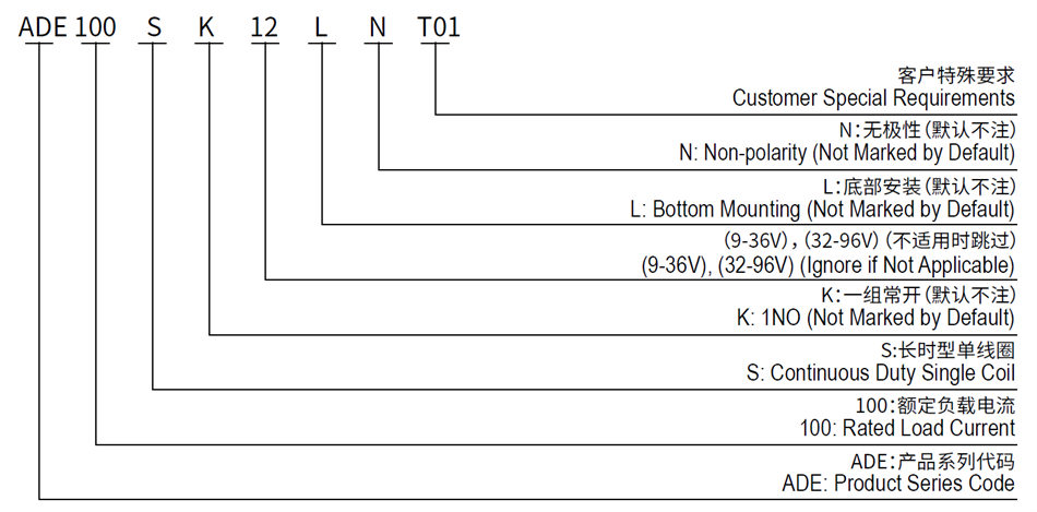
4. Model Coding
5. Wiring Diagram
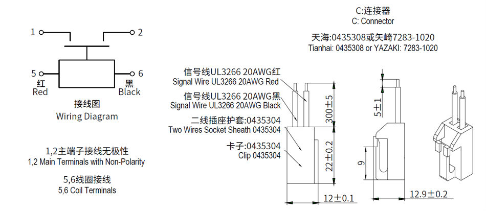
Note: The product main contact "1 " which is marked near the bolt is connected to the load " " terminal, and "2-" is connected to the load "-" terminal.
6. Outline Installation Dimension Drawing
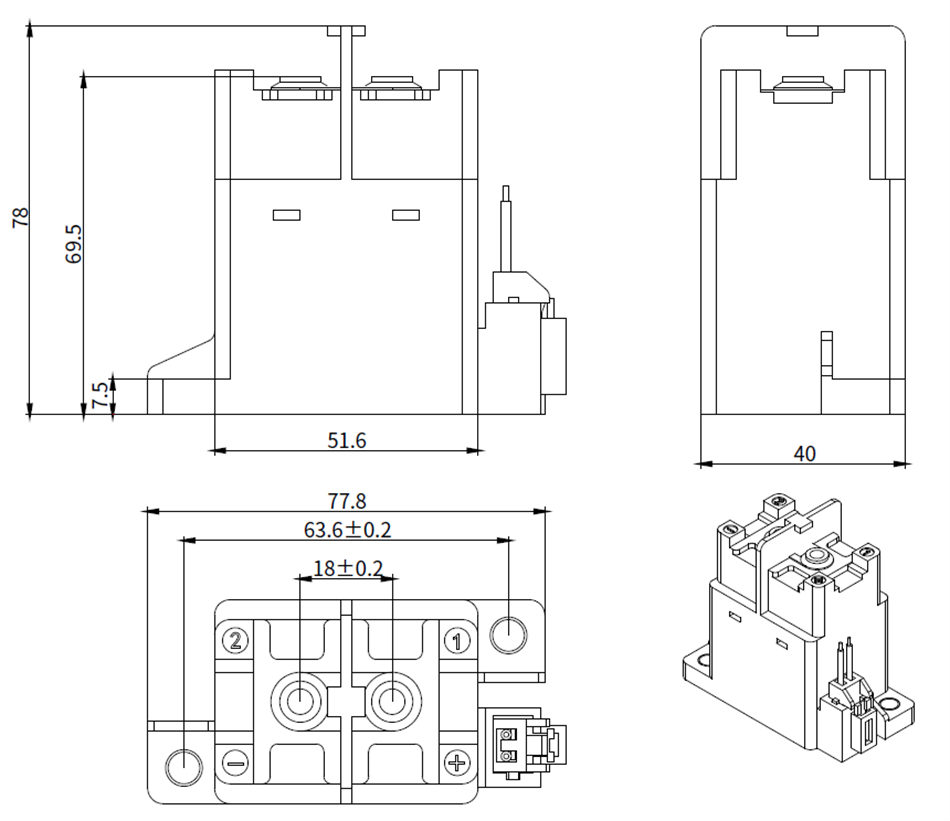
Note: These datas are only for customer selection reference, AOKAI has tried the best to ensure the accuracy of the information. Product specifications and parameters may be changed due to product improvement etc., they may be inconsistent because of not updated in time. For the specific parameters and performance of each product, please refer to the samples provided by AOKAI and the corresponding signed and controlled specification.
 English
