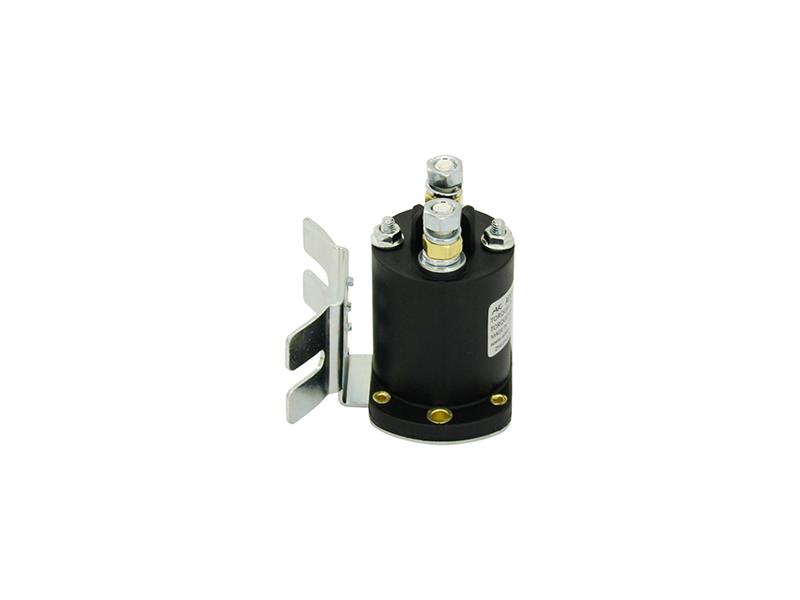
1. Introduction
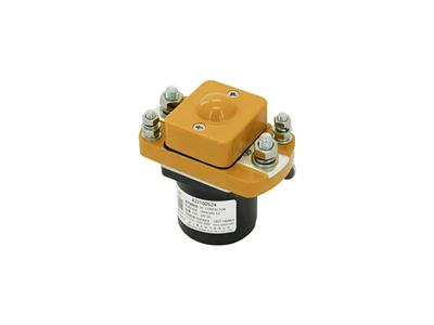
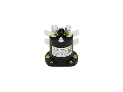
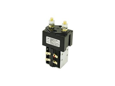
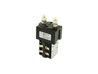
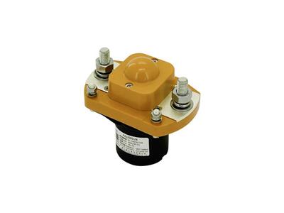
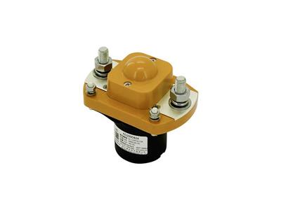
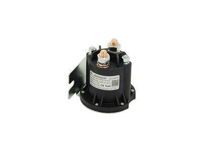
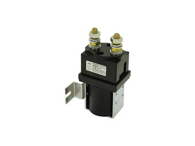
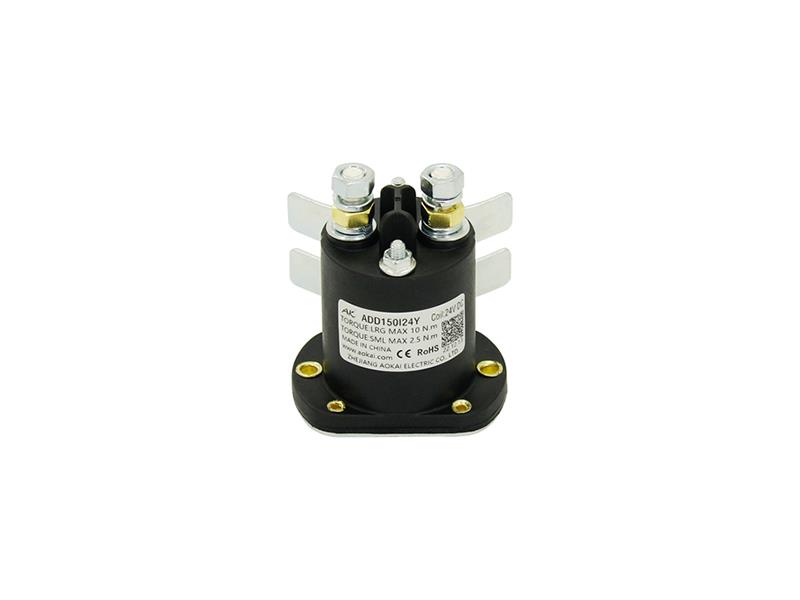
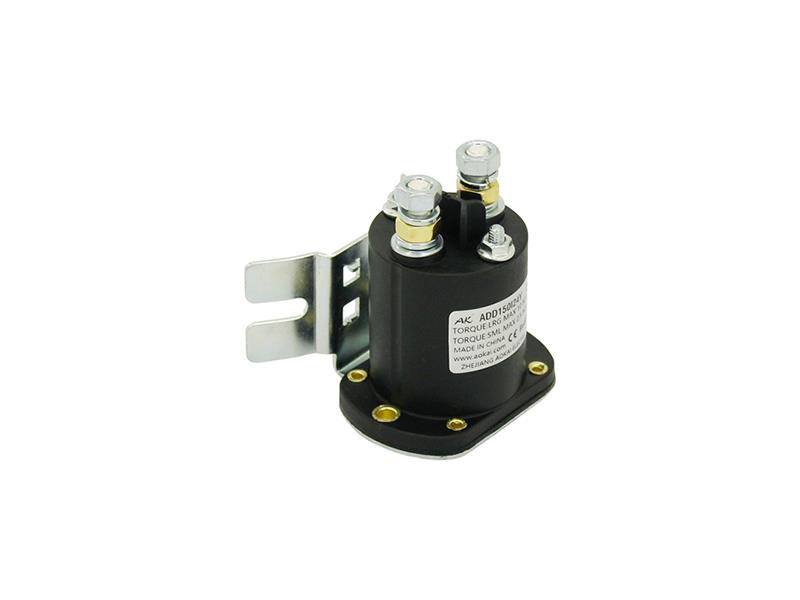
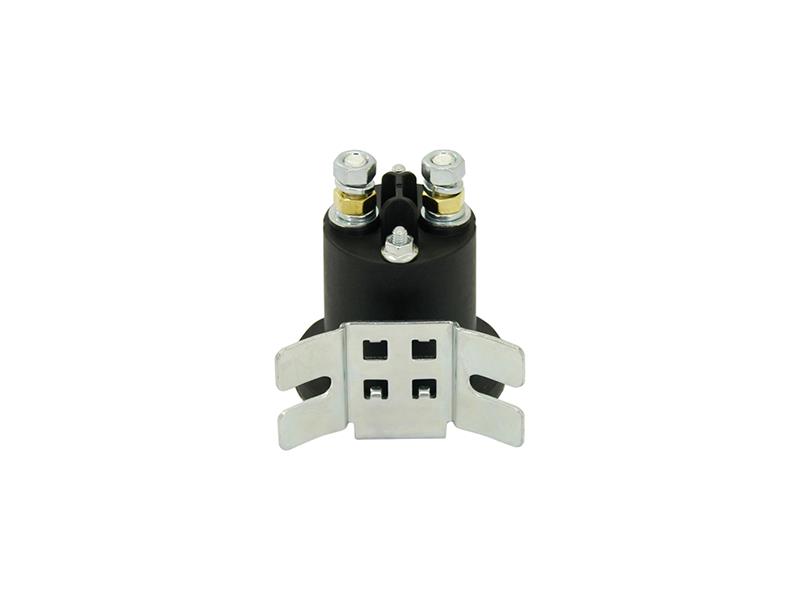
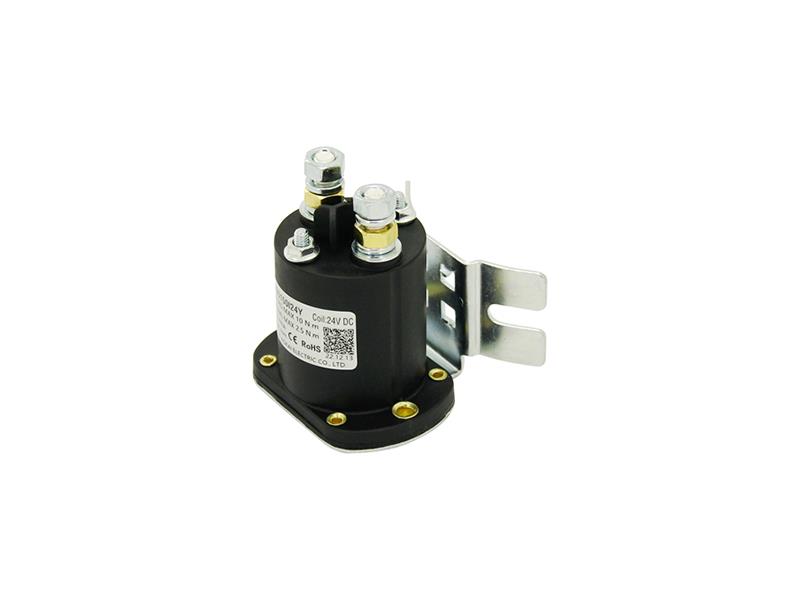
This series DC Contactor is used to control the electric circuit of hydraulic power unit systems, such as stackers, dock levelers, covered trucks, sanitation vehicles, automobile tail liftings, gull-wing doors, etc.
2. Features
• Intermittent 150A load.
• It has one set of normally open contact.
• Coil power consumption ≤22W.
• The insulation resistance is up to 100MΩ (1,000VDC), the withstand voltage between the contact and the coil is 2kV.
• IP protection level: IP67.
• Compliant with IEC 60664-1, GB/T14048.1 and GB/T14048.4 requirements.
• Compliant with RoHS (2015/863/EU), REACH (1907/2006/EC) requirements.
• Safety certificate: CE.
3. Specification
|
Performance Parameters (at 23℃) |
||
|
Contact Arrangement |
1K (1NO) |
|
|
Contact Resistance |
≤5mΩ |
|
|
Contact Voltage Drop |
≤80mV (at 80A) |
|
|
Overload Current |
≤7le, ≯1s |
|
|
Temperature Range |
-40℃~55℃ |
|
|
Load Terminal |
M6 External Thread |
|
|
Humidity |
5%~95%RH |
|
|
External Dimension |
62.5mmx61mmx67.8mm |
|
|
Operating Duty |
Intermittent |
|
|
Electrical Durability with Load (Resistive) |
≥50,000 Times (48V/150A) |
|
|
Load Wiring Torque |
6-8N.m |
|
|
Pull-In Voltage |
≤70% Us |
|
|
Drop-Out Voltage |
5%-40% Us |
|
|
Contact Bounce Period |
≤5ms |
|
|
Pull-In Time |
≤20ms |
|
|
Drop-Out Time |
≤10ms |
|
|
Dielectric Strength |
Between Main Contacts |
50Hz/60Hz 1,500VAC/1min |
|
Between Main Contacts and Coil |
50Hz/60Hz 1,500VAC/1min |
|
|
Insulation Resistance |
Initial State |
100MΩ 1min |
|
After Electrical Life |
50MΩ 1min |
|
|
Shock |
Stability |
20g (Power On) |
|
Strength |
50g |
|
|
Vibration |
3.5g, 10~200Hz, 1/2 Sine Wave (Power On) |
|
|
Mechanical Durability |
≥100,000 Times |
|
|
Coil Wiring Torque |
1.2-2.0N.m |
|
|
ADD150I Coil Parameters |
||||
|
Coil Voltage |
Pull-In Voltage |
Drop-Out Voltage |
Coil Resistance |
Coil Power Consumption |
|
12V |
≤70%Us |
5%-40%Us |
7.3Ω±10% |
20W±10% |
|
24V |
≤70%Us |
5%-40%Us |
26.8Ω±10% |
22W±10% |
|
36V |
≤70%Us |
5%-40%Us |
65Ω±10% |
20W±10% |
|
48V |
≤70%Us |
5%-40%Us |
134Ω±10% |
20W±10% |
|
60V |
≤70%Us |
5%-40%Us |
190Ω±10% |
20W±10% |
|
72V |
≤70%Us |
5%-40%Us |
272Ω±10% |
20W±10% |
4. Model Coding
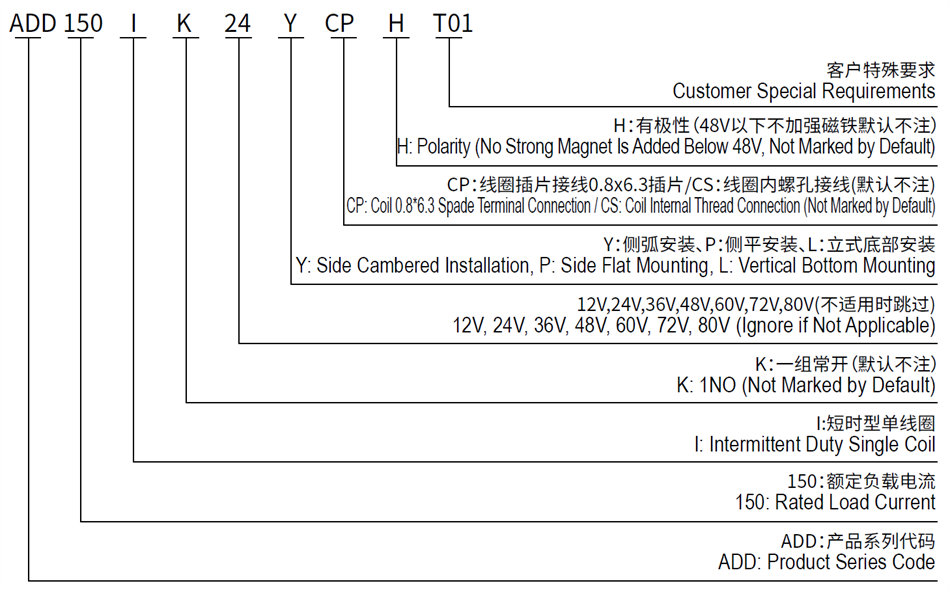
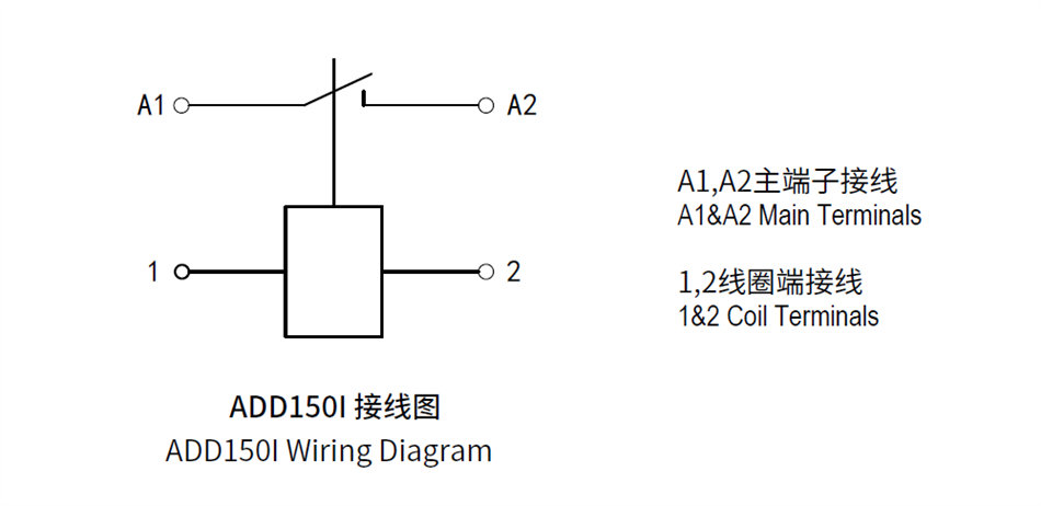
5. Wiring Diagram
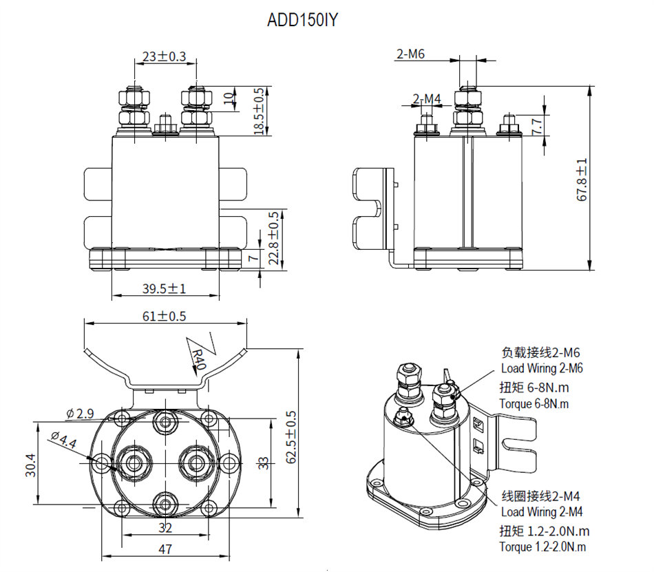
6. Outline Installation Dimension Drawing
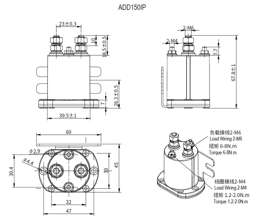
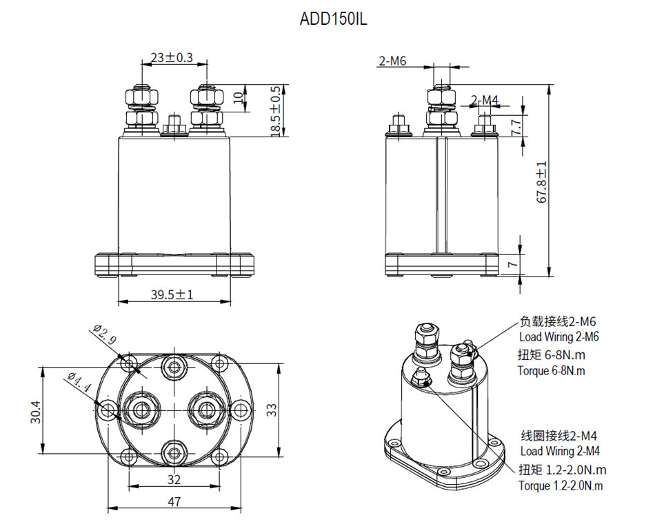
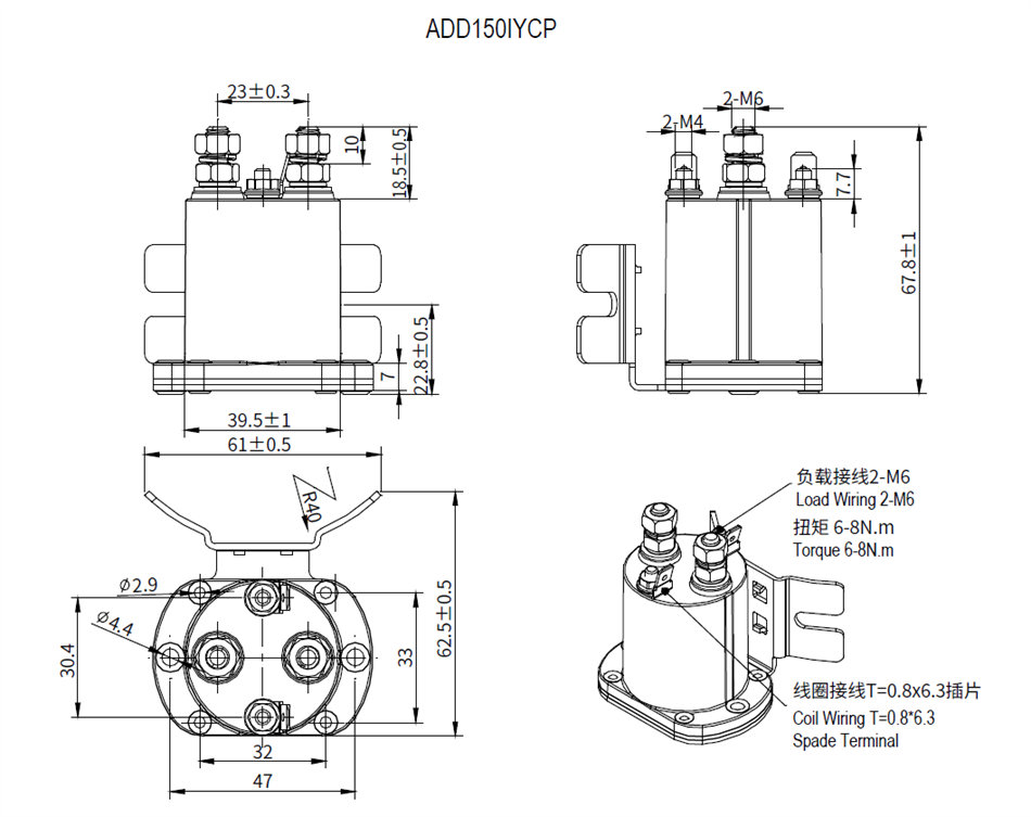
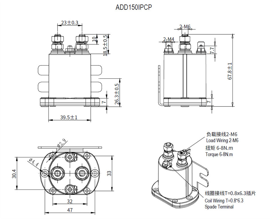
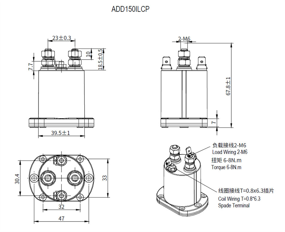
Note: These datas are only for customer selection reference, AOKAI has tried the best to ensure the accuracy of the information. Product specifications and parameters may be changed due to product improvement etc., they may be inconsistent because of not updated in time. For the specific parameters and performance of each product, please refer to the samples provided by AOKAI and the corresponding signed and controlled specification.
 English
